A Microwave Oven
The economic crisis seems to be over (in Spain): this is good for many reasons, but one kinda weird is that households are renewing their equipment, and one, me, can find old electronic apparel by the garbage containers: a real mine!
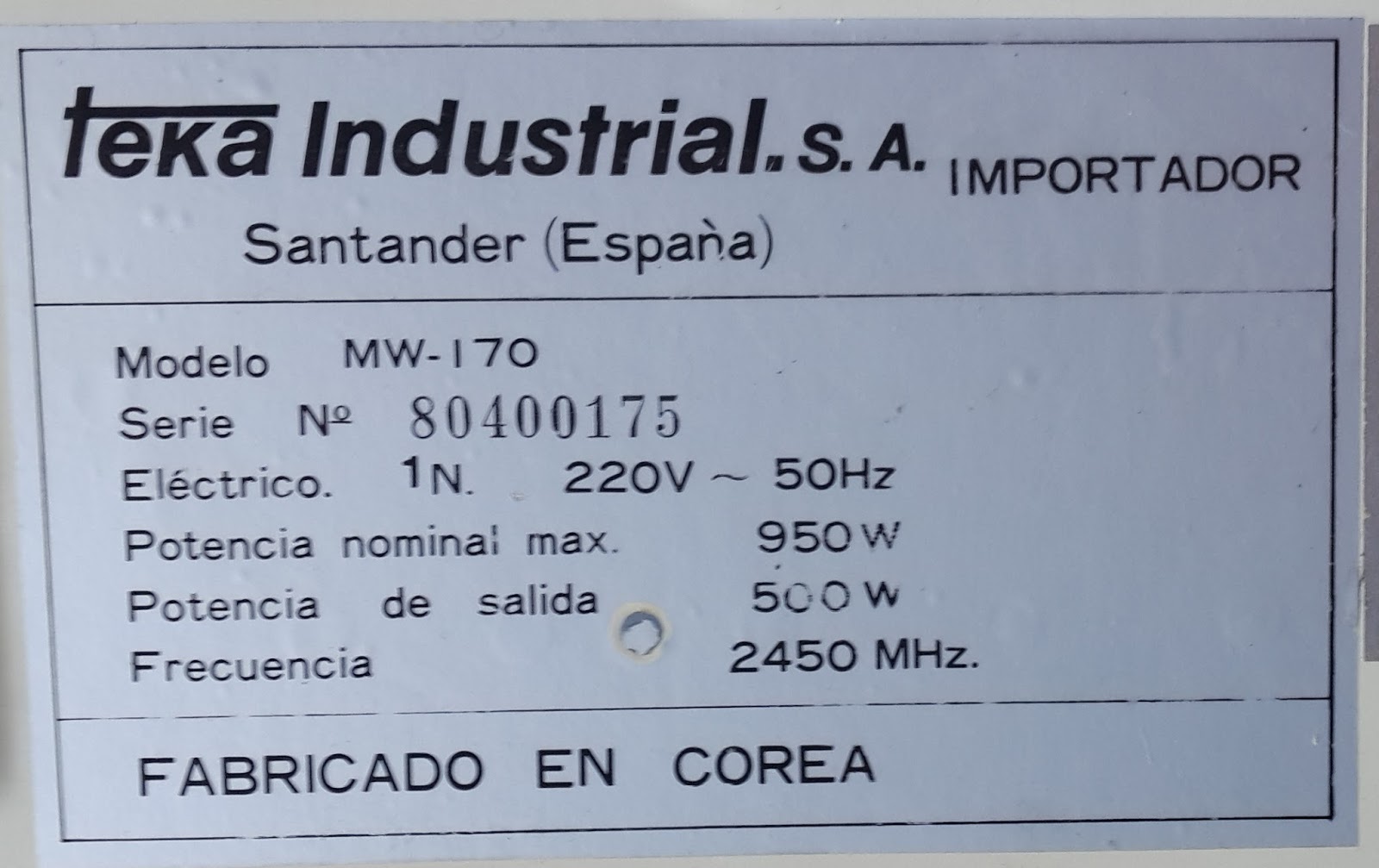
One of my recent findings is a microwave oven model Teka MW-170, made in Korea. I have not found any specific image of it in internet, and I disassembled the casing without taking all the necessary pictures, as I see now.

Model 170G, of which there is more information available and seems more recent, is similar but I have noticed at least several differences: MW-170 has one button to open the door plus another one to start the machine, and it has no turning table (the tempered glass is square!), while 170G does not have door-open and power-on buttons (just open and close the door), and it has a turning table. The documentation of the MW-170G also mentions a couple of heaters and additional switches which are not present in my model.
The specifications: 950 W nominal power, 500 W max output, working at 2450 MHz:

Wiring Diagram
Here the wiring diagram included in the machine:

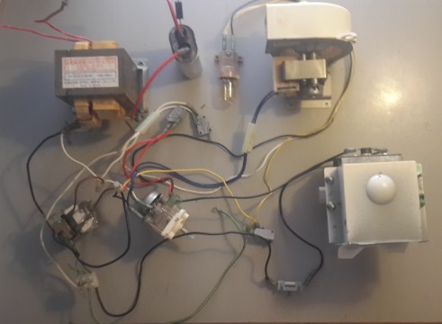
And a picture of the innings from the side:

I have dismantled the parts and the wiring diagram is OK:


Fan
The fan is connected in parallel to the timer. Its purpose is to cool down the magnetron.
The maker is Samsung, model RP-0650TE(N) 220V 50Hz.
The casing and the impeller are in plastic. The impeller diameter is approx 90 mm. I have not checked the speed.
The motor seems of the single-phase induction shaded-pole type.

Power Selector
The power selector is motorized.
The manufacturer is also Korea Nakagawa Elec. Ind. Co. Ltd. Model is DF-3CV24SI rated 15A at 250 VAC.
I have not found information on this motorized switch.
The drive is a small synchronous motor. The dial lever has 5 discrete positions, and its turning changes the position of an intermediate plastic wheel along the axis of the motor shaft. The motor turns this wheel, which is in discontinuous contact with the switch through a flapping plate. The shape of the wheel, and its position as regulated by the dial, control the amount of time per cycle of the motor that the switch is open/closed. This is how the power is controlled, just by varying the amount of time the magnetron is powered.


Transformer
The transformer is from Hankook Steel Works Co. Ltd. in Korea. Model is H-5220-5(55VA) 220V 50 Hz. It is labelled as "DANGER HIGH VOLTAGE", "DISCHARGE CAPACITOR BEFORE SERVICING".
The transformer has two secondary windings, but no indication of the output voltage. Internet references point to 3-4 kV.
Magnetron and HV Capacitor
The magnetron used in the oven is from Samsung, model OM55A (20), many of which can still be found in ebay and similar places.


This webpage, on spares and replacement parts, defines it with the following features:
- voltage: 4.1 kV
- standard type (30 mm of antenna, upper box 80*95 mm)
- J configuration ("vents and mounting ears opposite filament leads")
- 700-850 watt
- 35 mm hole center.
From that page:

The magnetron is the core of the machine, the generator of the microwaves that heat the stuff.
The physics behind it are moderately advanced, but without entering in details the principles can be described here.
A high voltage is provided to an anode/cathode element. The cathode, a rod bar, is also heated, and this facilitates the emission of electrodes from it. The anode is ring shaped around the cathode. A magnetic field is applied parallel to the cathode. The electrons tend to jump from the cathode due to the differential electrical voltage, and being charged particles moving in a magnetic field, forces appear on them. The result of both electric and magnetic fields is that the electrons follow spiral trajectories in their way from the cathode to the anode.
The anode has several cavities in its body (these are called "cavity magnetrons"). The interference of the moving electrons and the cavities create certain electromagnetic resonance, which is manifested as microwave radiation. This radiation is collected with an antenna, and conveyed to the oven through a "wave channel".
An aluminium turning wheel ("stirrer fan") in the wave conduit helps distributing the radiation in all directions in the oven.
The magnetron requires DC voltage, and for this reason are provided the large HV capacitor and the diode: to rectify the AC current powering the magnetron into a low ripple, high voltage direct current.
Industrial applications have other power sources, pulsed or switched, but domestic appliances follow the conventional solution with capacitor and diode.
The capacitor is from Samsung, labelled H.V. CAPACITOR SCH-212904A1, 2100 W VAC, 0.90 uF T-70, INTERNAL RESISTOR, NO PCBs.
The capacitors are fitted with internal resistors to allow the discharge when not in use. In any case, the capacitor should be discharged prior to handling it, with a suitable resistor (see here).
The diode is labelled "HVR-1X 3", "SK 8120".

Readings
If you look for some more technical information on the cavity magnetron, see here.
A good and detailed page on microwave ovens here.
And a couple of books, which I have not checked:
- Davidson, Homer L. Microwave Oven Repair, 2nd edition. Tab Books Inc., 1991.
The economic crisis seems to be over (in Spain): this is good for many reasons, but one kinda weird is that households are renewing their equipment, and one, me, can find old electronic apparel by the garbage containers: a real mine!
One of my recent findings is a microwave oven model Teka MW-170, made in Korea. I have not found any specific image of it in internet, and I disassembled the casing without taking all the necessary pictures, as I see now.

Model 170G, of which there is more information available and seems more recent, is similar but I have noticed at least several differences: MW-170 has one button to open the door plus another one to start the machine, and it has no turning table (the tempered glass is square!), while 170G does not have door-open and power-on buttons (just open and close the door), and it has a turning table. The documentation of the MW-170G also mentions a couple of heaters and additional switches which are not present in my model.
The specifications: 950 W nominal power, 500 W max output, working at 2450 MHz:
Wiring Diagram
Here the wiring diagram included in the machine:


I have dismantled the parts and the wiring diagram is OK:
Operation and Components
Fuse
It is labelled "BUSS MDA 7" and "250 VOLT". It is a ceramic type fuse, similar to this one.
Thermal Cut-Out
It is mounted on one side of the magnetron box. It is labelled in the metal face: "CS-7SA", "2208", "150", and in the plastic cap "CLINAC", "CS 7".
It is a bimetallic thermostat, whose typical applications include microwave ovens, as per this page. The switch is rated for 7.5 A at 250 V.
The switch is normally on, and is disconnected when the temperature exceeds the set value, likely 150 ºC (not checked).


Both the fuse and the thermal cut-out can independently open the circuit.
Lamp
The lamp is incandescent, mounted on a plastic lamp holder labeled "BOSUNG", "BS77", "2A 250V T180". The lamp is 20 W, from Okusun, for E12 socket (narrow screw, candelabra type) and bulb shape T8 (tubular, 1 inch diameter).
As per the wiring diagram, as soon as the timer is activated the light will also be lit on, regardless of any other switch (exception made of the thermal protection).

Switches
The oven has five on/off switches: two "manual" (open/close door and power on/off), one safety element (the "monitor switch"), and two switches related to selectors (power level and timer).
The three independent switches are from Yamatake-Honeywell, series micro:
- the primary switch is model V-5130D 2-88-P Y111, NO (normal open), rated 16A at 250 VAC,
- the secondary switch is model V-5132D 12-87P Y111, also NO and same rating,
- the monitor switch is model V-5423D-049 8812J, T85, NC (normal closed), rated 5A at 250 VAC.
They seem similar to these more modern ones.

The switch on the variable motor setting the power level is from Matushita, model AV53606 T105, NO, rated 15A at 250 VAC. It is fixed to the motor.

The last switch, for the timer, is incorporated inside the timer.
It is worthy looking again at the wiring diagram for the control system for the function of the "monitor switch".
The diagram shows that if the timer and primary switches are closed, there will be a short through the monitor switch. The occurrence of this short is a protection introduced after a US safety standard required in 1974 an interlock monitor switch (also called safety switch, short switch, sensing switch or failure detector switch). The principle is that under normal conditions opening the door should cut the power to the magnetron. The safety interlock assures that if the magnetron is powered and the door is opened, that is in case of failure of the door switch, then a short will occur which will disable the appliance before the door is opened too much and dangerous levels of microwave radiation escape.
I did not keep the mechanical part of the switches, but I assume the following detailed operation: the primary switch (the door switch) operates inversely to the monitor switch, with a slight time delay controlled mechanically, so they are not in closed position simultaneously unless in case of emergency: prior to closing the primary switch, the safety switch is opened; and slightly after opening the main switch, the safety switch is closed.
Anyhow, the amount of radiation emitted by a leaky microwave oven is very small, as indicated in these webpages of the WHO and the FDA.
Timer
The timer is set in a progressive scale: 90º corresponds to 3 min, 180º to 10 min, and 270º to 30 min, up to a maximum of 35 min, following approx. a logarithmic scale.

The timer operates as normally open; it closes the switch when the timer is on, and it remains closed until it reaches the set time, when it opens again. When the time is reached, a bell is mechanically hit. If the dial is turned on, then the switch is closed regardless of whether the timer is powered or not.


The timer is from Korea Nakagawa Elec. Ind. Co. Ltd, model "SE-35MF240IB" with a switch capacity of 12 A and 250 V. The manufacturer does not seem to produce this model any more, and I have also not found any reference to it in internet.
The fan is connected in parallel to the timer. Its purpose is to cool down the magnetron.
The maker is Samsung, model RP-0650TE(N) 220V 50Hz.
The casing and the impeller are in plastic. The impeller diameter is approx 90 mm. I have not checked the speed.
The motor seems of the single-phase induction shaded-pole type.

Power Selector
The power selector is motorized.
The manufacturer is also Korea Nakagawa Elec. Ind. Co. Ltd. Model is DF-3CV24SI rated 15A at 250 VAC.
I have not found information on this motorized switch.
The drive is a small synchronous motor. The dial lever has 5 discrete positions, and its turning changes the position of an intermediate plastic wheel along the axis of the motor shaft. The motor turns this wheel, which is in discontinuous contact with the switch through a flapping plate. The shape of the wheel, and its position as regulated by the dial, control the amount of time per cycle of the motor that the switch is open/closed. This is how the power is controlled, just by varying the amount of time the magnetron is powered.


Transformer
The transformer is from Hankook Steel Works Co. Ltd. in Korea. Model is H-5220-5(55VA) 220V 50 Hz. It is labelled as "DANGER HIGH VOLTAGE", "DISCHARGE CAPACITOR BEFORE SERVICING".
The transformer has two secondary windings, but no indication of the output voltage. Internet references point to 3-4 kV.
Magnetron and HV Capacitor
The magnetron used in the oven is from Samsung, model OM55A (20), many of which can still be found in ebay and similar places.


- voltage: 4.1 kV
- standard type (30 mm of antenna, upper box 80*95 mm)
- J configuration ("vents and mounting ears opposite filament leads")
- 700-850 watt
- 35 mm hole center.
From that page:
The magnetron is the core of the machine, the generator of the microwaves that heat the stuff.
The physics behind it are moderately advanced, but without entering in details the principles can be described here.
A high voltage is provided to an anode/cathode element. The cathode, a rod bar, is also heated, and this facilitates the emission of electrodes from it. The anode is ring shaped around the cathode. A magnetic field is applied parallel to the cathode. The electrons tend to jump from the cathode due to the differential electrical voltage, and being charged particles moving in a magnetic field, forces appear on them. The result of both electric and magnetic fields is that the electrons follow spiral trajectories in their way from the cathode to the anode.
The anode has several cavities in its body (these are called "cavity magnetrons"). The interference of the moving electrons and the cavities create certain electromagnetic resonance, which is manifested as microwave radiation. This radiation is collected with an antenna, and conveyed to the oven through a "wave channel".
An aluminium turning wheel ("stirrer fan") in the wave conduit helps distributing the radiation in all directions in the oven.
The magnetron requires DC voltage, and for this reason are provided the large HV capacitor and the diode: to rectify the AC current powering the magnetron into a low ripple, high voltage direct current.
Industrial applications have other power sources, pulsed or switched, but domestic appliances follow the conventional solution with capacitor and diode.
The capacitor is from Samsung, labelled H.V. CAPACITOR SCH-212904A1, 2100 W VAC, 0.90 uF T-70, INTERNAL RESISTOR, NO PCBs.
The capacitors are fitted with internal resistors to allow the discharge when not in use. In any case, the capacitor should be discharged prior to handling it, with a suitable resistor (see here).
The diode is labelled "HVR-1X 3", "SK 8120".

Readings
If you look for some more technical information on the cavity magnetron, see here.
A good and detailed page on microwave ovens here.
And a couple of books, which I have not checked:
- Davidson, Homer L. Microwave Oven Repair, 2nd edition. Tab Books Inc., 1991.
- Gallawa, J. Carlton. The Complete Microwave Oven Service Handbook: Operation, Maintenance. Prentice Hall, 1989.
Hi,tell me please what to do with Russell Hobbs RHM2362S, the motor that twisted the plate is dead. The oven is operating normally, it is warming the food, but the plate does not turn due to which the heating is uneven. What is most offensive, the guarantee ended just a week ago.
ResponderEliminar