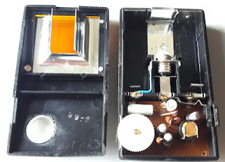
This is a “Warnblinkleuchte für Auto+Fussgänger Taschenlampe”:
a hazard-warning pocket flashlight for car and pedestrians. It is a Made in Germany personal safety lamp
from the early 70s. Its purpose is simple:light on a warning (orange, flashing light)
when faced against the beam of a facing car. The user, a walker on a
road at night, wears it and it starts blinking as soon as detects the arriving
car.
There is a curious set of vintage ads on it, for instance: PopularMechanics (1971), MotorBoating & Sailing (1971) and AmericanMotorcyclist (1971).
Interestingly, one of the ads described it as “the world’s
first fully automatic transistorized flash warning signal”!
Operation
The lamp works as intended: it can be set on by a separated
switch which bypasses the light sensor and the intermittency circuitry, and it
also starts blinking when the light intensity increases, with a sensitivity
that can be regulated with a wheel.
I have not tested it at night or on a road: it is an
incandescent 3V lamp, so really not a powerful safety device – at least not by
today’s standards.
Parts
The circuit is on a PCB which cannot be easily removed from
the lamp, so I can’t show the actual schematics. The parts can, however, be
identified:
- A direct switch to turn the light on,
- A variable resistor, on a wheel, with a switch,
- The light sensor,
- Four transistors, and
- Four resistors plus one electrolytic capacitor.
The variable resistor provides up to 5.5 kOhm. Three of the
resistors are clear: 270, 39k and 10k, but the fourth has only two bands (2-0),
larger than usual, plus an even larger golden band at the other end. The
capacitor is labelled “5 MFD – 3V”.
Three of the transistors are marked with OC 305/1. This
seems to be (here and here)
equivalent to an NTE158 PNP transistor (here and here).
It is a Germanium-based device, and there is still a market for it (here and here).
The package is in metal, but they seem slenderer than a TO-18. The fourth
transistor is even longer and unmarked (I assume it's a transistor because it is three legged...).
The light sensor is a LDR (light dependent resistor).
I have measured approx. xx Ohm at 60 lux and above xx Ohm at 400 lux.
Schematics
As mentioned above it is not possible to see the back of the
PCB. A simple possibility with an LDR, a variable resistor and a PNP is:
The blinking may be controlled with an astable circuit with PNPs (here for NPN), like this one (which clearly does not match the list of parts).
(I have not checked, but it seems likely that the frequency of blinking is affected by the light intensity and the position of the regulating wheel - yes, it is: I have checked).


No hay comentarios:
Publicar un comentario