1 Description
This is a SCART board from an old DVD player (if I'm not mistaken). The board size is 80*25 mm.
Some pictures:


The board has several marks:
LFM 200492-0001
76VCA
94V-0
Besides the female SCART connector it has two male pin sockets: one for 8 pins/cables, the other for 5.
2 Simulation
The circuit is modeled in QUCS, and can be found here.
A snapshot of the schematics:
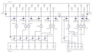
There are a number of parts which seem to be ferrite beads: they are black cylinders, unmarked, the PCB labels them as FBNNN, and it makes sense that there are filters for signal cleaning. Their properties are unknown to me and I have simulated each of them as a subcircuit, with the model and properties mentioned here for one example. The impedances of all them is in the range of 0.5 ohm, as measured by my DMM.
There are also some SMD parts whose identification is unclear:
- ZDNNN, which I assume are Zener diodes protecting the line in case of voltage peaks (all are marked E29 except one (ZD135) which is H38).
- CNNN, which I asume are capacitors, but of unknown capacitance.
3 SCART
See here for information on the connections. The standard, EN 50049, is here.
There are several SCART connectors (at least three as per this source, in Spanish).
Pins 1, 2, 3 and 6 are for the audio (L and R, IN and OUT); the Zener protects lines 1 and 3 which are both OUT. This side goes to pin connector RB203.
All video signals are protected by Zener diodes, and go to pin connector RB202.
As per the pins used on the board, this is a type 1 connector. Pins (7, 11, 15) form the RGB channels IN, and pin 19 for composite video OUT; pins 8 and 16 control the communication acording to voltage levels (see here).
Voltage levels are (source here):
- Audio: 0.5 Vrms
- Video RGB: 0.7 Vrms
- pin 8:
* 0 - 2 V = no signal, or internal bypass
* 4.5 - 7 V (nominal 6 V) = widescreen (16:9) signal; (5-8 V as per this source).
* 9.5 - 12 V (nominal 12 V) = normal (4:3) signal
- pin 16:
* 0 - 0.4 V = composite
* 1 - 3 V (nominal 1 V) = RGB
- pin 19: 1 V
All impedances from teh SCART female connector to the internal pin connectors are low (below 1 ohm as per my DMM).
No hay comentarios:
Publicar un comentario