martes, 1 de mayo de 2018

BLINKILUX


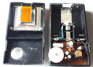
This is a “Warnblinkleuchte für Auto+Fussgänger Taschenlampe”: a hazard-warning pocket flashlight for car and pedestrians. It is a Made in Germany personal safety lamp from the early 70s. Its purpose is simple:light on a warning (orange, flashing light) when faced against the beam of a facing car. The user, a walker on a road at night, wears it and it starts blinking as soon as detects the arriving car.


There is a curious set of vintage ads on it, for instance: PopularMechanics (1971), MotorBoating & Sailing (1971) and AmericanMotorcyclist (1971). 
 

Interestingly, one of the ads described it as “the world’s first fully automatic transistorized flash warning signal”!
There seems to be an active market for it, for instance here, here, here, here.

Operation
The lamp works as intended: it can be set on by a separated switch which bypasses the light sensor and the intermittency circuitry, and it also starts blinking when the light intensity increases, with a sensitivity that can be regulated with a wheel.
I have not tested it at night or on a road: it is an incandescent 3V lamp, so really not a powerful safety device – at least not by today’s standards.

Parts
The circuit is on a PCB which cannot be easily removed from the lamp, so I can’t show the actual schematics. The parts can, however, be identified:
- A direct switch to turn the light on,
- A variable resistor, on a wheel, with a switch,
- The light sensor,
- Four transistors, and
- Four resistors plus one electrolytic capacitor.

The variable resistor provides up to 5.5 kOhm. Three of the resistors are clear: 270, 39k and 10k, but the fourth has only two bands (2-0), larger than usual, plus an even larger golden band at the other end. The capacitor is labelled “5 MFD – 3V”.
Three of the transistors are marked with OC 305/1. This seems to be (here and here) equivalent to an NTE158 PNP transistor (here and here). It is a Germanium-based device, and there is still a market for it (here and here). The package is in metal, but they seem slenderer than a TO-18. The fourth transistor is even longer and unmarked (I assume it's a transistor because it is three legged...).
The light sensor is a LDR (light dependent resistor). I have measured approx. xx Ohm at 60 lux and above xx Ohm at 400 lux.


Schematics
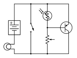
As mentioned above it is not possible to see the back of the PCB. A simple possibility with an LDR, a variable resistor and a PNP is:
The blinking may be controlled with an astable circuit with PNPs (here for NPN), like this one (which clearly does not match the list of parts).

(I have not checked, but it seems likely that the frequency of blinking is affected by the light intensity and the position of the regulating wheel - yes, it is: I have checked).

viernes, 27 de abril de 2018

Coffe Machine Philips HD 5670/A

This seems to be a "mildly old" coffee machine: it has been at my family's home for perhaps 20 years, and I could not find anything on it at internet (besides a complain on a second-hand unit).

It is a bulky unit (almost 30*30*15 cm), which does not use capsules (too modern!): it is a conventional, manual espresso machine. It requires that the granulated and toasted coffee is placed on a cup which is then placed against the steam outlet or grouphead. It also has a separated hot steam supply (the steam wand) for heating the milk (or the water).


Main Parts
The machine has mechanical, hydraulic and electrical parts, in three main systems:
- A pump, which receives (sucks) the water from the water tank and pumps it into a boiler.
- A boiler, which creates pressurized hot steam.
- The electrical controls, with sensors and switches on the other parts.

Besides its very simple control, operation-wise is similar to other coffee machine that I described here.


Schematics
The electrical part is very simple, as indicated in the attached schematics.
The operation is straight: switch S0 starts the machine on/off and the heating resistor (R1), while switch S1 sets the pump in operation (M1), creating the flow of steam. Switch S2 is in parallel to one of the thermal sensors in the boiler (TH4), so it bypasses its function with a kick of additional steam.
The light RD1 (red) is on as soon as the machine is connected (S0), and the light OR1 (orange) is on when the heating resistor is active.

The Pump
The pump is model CS M3637 from Eaton, Mod CP2, with a power of 70 W working at 25-60ºC. It is of the vibrating or solenoid type, described in another post. (Eaton is a giant, and it seems they do not manufacture these pumps anymore; there are a number of internet sites on these pumps and spares: one example here). It is mounted on rubber pads, and it is protected with a thermal fuse (Microtemp 4204A ZKAFZ 98 C; TH2) attached to the body of the pump. (Here on the operation and coding of these thermal fuses, although this one seems to be older).

The Boiler
Made in, in two pieces, bolted (th boiler in aluminium, the grouphead in inox). There is no mark on it. It has a release valve, manually regulated for the steam wand.


The heating resistor (R1) has approx. 43 ohm, which yields a power of some 1,150 W at 220 V (rated 1,260 W).
There are three temperature sensors in contact with the body: two switches from Campini TY60 T180 (TH3 and TH4), and one thermal fuse Microtemp 4300A ZHAHG 152 C (TH1).
(I'm curious about the two thermal switches and the temperature distribution in the boiler, but I have not yet a thermal camera!)
Here on the operation and coding of the thermal fuse, although this one also seems to be older; and here on the specifications of the Campini thermostat switch (“single pole thermostat with snap-action disc”).


The Switches
The three switches are mechanical, of the push type, normally open, with one pole. The manufacturer is ROLD, series CM. S0 and S1 are model E1026 A1 (they retain the closed position when pushed); Switch S2 is model E2015 A1 (does not retain the position when pushed).
ROLD is an Italian manufacturer, a “leader in the manufacture of components for household appliances”. Their webpage does not have catalogues.


sábado, 7 de abril de 2018

Toaster Kenwood TTP102

I found this toaster a couple of weeks ago, with the main cord cut: here is the “disemboweling”!

The Toaster
The manual is here (from ManualsLib).
It is a simple, 2 slice toaster, with "600-800 W", vertical positioning and some controls which I’ll describe later.
It seems to be out of sale in some places (Amazon-UK, Amazon-DE, Kenwood-DE, Kenwood-PAK, Kenwood-ES) but it is available elsewhere (IND, UK, MasterSparesOnline, PAK, ebay-DE).


The Operation
The device is relatively simple, with 5 “controls”:
- the slice lowering lever,
- the variable "browning control",
- the cancel, defrost and reheat buttons (illuminated).


The Inside
The electrical parts are organized in 4 elements:
- the power switch, with a solenoid,
- the variable resistor (“browning control”),
- the 3 heating panels, and
- the control PCB (with the cancel, defrost and reheat buttons and the timers).

The following pictures show the sequence of opening the toaster.


There seems to be a market of spares for this unit, mostly in the UK (PartMaster, 4Kenwood, BuySpares, eSpares).


The Power Switch and Solenoid
Lowering the slices with the main lever closes a switch, that feeds a solenoid. The lever is then attracted to the solenoid and when the power supply to the solenoid is open, a spring in the lever makes it jump-up, with the slices.

The solenoid is labelled “TA8018”. It is fed from the control board, which supplies it with DC current.
The switch is mounted on a board, with no fuse.


The Variable Resistor
It is a linear variable resistor, labelled “B200K” and I have measured from 300 to 200 kohm. One of the bands on the sides of the support is conductive, the other resistive.


The Heating Panels
There are three heating panels, connected in series. One of them is connected with a single wire to the control board.


I have measured about 25 ohm for the ones on the sides, and 30 ohm in the central one. The heating power is therefore 600 W at 220 V (not 800 W).
Based on the length of the wire, the unit resistivity is approx. 150 ohm/m.
The support is a sort of micaceous paper.
The panels are labelled “TA8018M”.


The Control Board
The control board is connected to:
- the power switch for line,
- the end of the wire at the first heating panel for “neutral”,
- the solenoid, and
- the variable resistor (the “browning control”).


The board supports three push buttons with light, but its core is a chip: TN0841B2 A0201D, which I described here.
The board is labelled as “TA8018GS-D-11”, "E123995", "KB-3151" and “2006-7-15 REV:A”, for which I have not found any reference.


The schematics is as follows:
At the connector:
- 1 is for the "ground" at the heater,
- 2 and 4 are for the solenoid, and 
- 3 is for the AC line.

(The pins of the chip are not correctly identified).